

Lithium-ion (“Li-ion”) batteries are ubiquitous - they are found in consumer electronics, electric vehicles (“EV”) and even stationary storage systems. Part of this is due to the high gravimetric and volumetric energy densities of Li-ion batteries, which can in part be explained by the small ionic radius of a lithium ion and corresponding low weight.
They are also of increasing importance in decarbonization to support electrification and adoption of renewable energy. Hence, it is crucial to understand how Li-ion batteries work; for example, how exactly does a battery charge and discharge? Why do batteries degrade?
In this essay, I explore the workings of conventional Li-ion batteries.
The tl;dr for the layman:
Fast charging your Li-ion battery, especially in cold temperature, can be detrimental to your battery's health
Do not overcharge or overdischarge your Li-ion battery. Keeping it to a range of 30-70% is probably advisable
Avoid storing Li-ion batteries at high temperature or high state of charge
Otherwise, the rest of the essay will be organized into the following sections:
Structure of a Li-ion cell
Working principles of Li-ion cells
Li-ion cells, modules and packs
Chemistries of anodes
Chemistries of cathodes
Degradation and aging
Thermal runaway
Strategies to mitigate Li-ion battery failure
This essay may get technical, so some understanding of chemistry and physics is useful. I’ve also tried my best to link to the sources used; if I’ve left yours out, please let me know and I will include them.
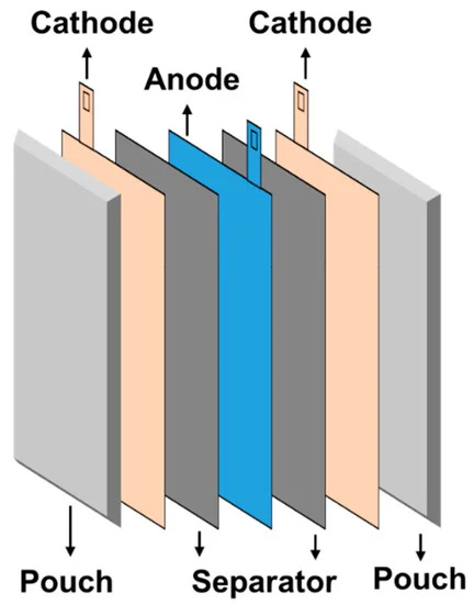
Structure of a Li-ion Cell
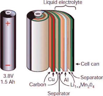
The typical Li-ion cell, shown in Figure 1, usually has the following components:
Cathode
Anode
Separator
Electrolyte
Current collectors
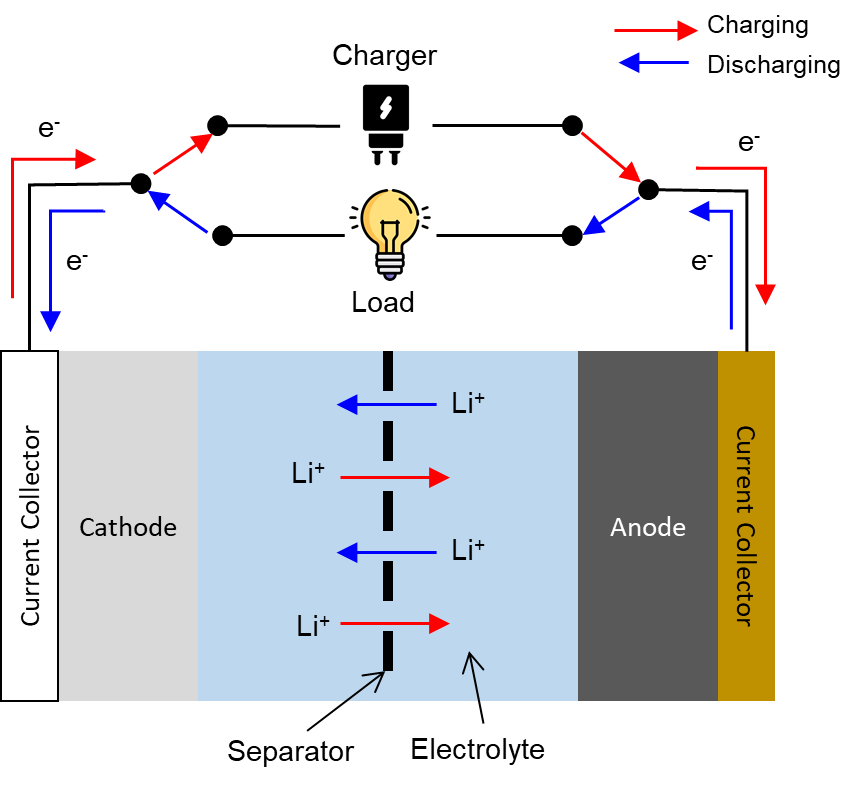
Cathode
The cathode is typically made of a transition metal (e.g., nickel, iron) oxide. Ideally, the transition metal ion in the cathode should have a high redox potential (i.e., it accepts electrons easily) so that the output voltage of the Li-ion cell is high.
During the charging and discharging process respectively (as further explained below), the cathode can undergo reversible delithiation and lithiation of lithium. Ideally, the cathode’s structure should allow lithium ions to diffuse well (i.e., move fast). The diffusibility of lithium in the cathode and anode takes time and is a determining factor in how fast a Li-ion cell can charge.
Anode
Graphite is usually used to make the anode as it is structurally stable, has low electrochemical reactivity, is relatively low cost, and has a relatively large capacity for insertion of lithium ions. As we will see later, this is an important point as it determines the energy density of the battery.
Electrolyte
Most Li-ion cells have electrolytes that contain a lithium hexafluorophosphate (“LiPF6”) salt. The LiPF6 salt is then usually dissolved in a solvent which is a mixture of linear and cyclic carbonates (e.g., ethylene carbonate (“EC”) and dimethyl carbonate (“DMC”)).
The electrolyte is important as it allows lithium ions to shuttle back and forth between the cathode and anode. It should also have the following properties:
High ionic conductivity;
Ability to operate over a wide range of electrical potentials; and
Thermally stable over a wide range of operating temperatures.
Separator
The separator prevents electrons from passing through and only lets ions pass through its pores. In general, the separator should have the following properties:
Good electrochemical stability;
Good electrolyte absorption and retention to improve ion transport;
High strength to withstand mechanical stresses during the battery operations; and
Low thickness to minimize the distance between the anode and cathode and hence lower internal resistance.
Separators can also be designed or chosen such that once the Li-ion cell reaches a temperature that is too dangerous (e.g., during thermal runaway), the separator can soften and close its pores, hence becoming non-conducting and ceasing battery operations to prevent fire hazards.
Separators today are typically polyethylene and polypropylene.
Current collectors
The current collectors at the cathode and anode are usually made of aluminum and copper respectively. They conduct electrons between the electrodes and the terminals of the cell.
Working principles of Li-ion cells
As its core, a Li-ion cell is an electrochemical device in which redox reactions take place reversibly. These redox reactions, which occur because the redox potential between the cathode material and anode material is different, allow the conversion between electrical and chemical potential energy and the storage of the latter in the electrodes.
To calculate the open circuit voltage of a Li-ion cell, the following equation is used (source: Liu et al.):
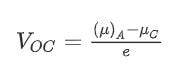
The difference between μA (for the anode) and μC (for the cathode) is the electrochemical potential difference. Dividing this difference by e, the magnitude of the electronic charge, gives the open circuit voltage (VOC) of a cell.
The voltage of the cell is an important parameter as it, together with the specific capacity of the anode and cathode, determine the energy density of the Li-ion cell. Through the equation ΔE = qΔV, we know that voltage (ΔV) is energy (ΔE) per unit charge (q). Furthermore, the number of charges (q) can be increased if the specific capacity of the electrodes are higher. Hence, the higher the potential difference between the cathode and the anode, and the specific capacity of the electrodes, the higher the energy stored in the cell.
Charging a Li-ion cell
In general, when a Li-ion cell is charged, lithium ions must move from inside the cathode crystal, pass through the electrolyte, and then reach the anode. Energy must be supplied by an external source to cause this.
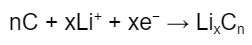
The reaction at the cathode is:

where M is a transition metal (e.g., cobalt, nickel, manganese). Lithium diffuses out of the cathode crystal and moves into the electrolyte while an electron moves via the external circuit into the anode (see Figure 1). Note that as lithium diffuses out from the ionic lattice of the cathode, the transition metal is oxidized to ensure charge neutrality at the cathode; this is why transition metals are important - their multivalency allows for multiple oxidation states to support the redox reactions.
Over at the anode, the reaction is:
When LixCn is formed, the graphite is said to be “lithiated” via a mechanism known as intercalation. During intercalation, lithium ions insert themselves into the graphite matrix (Figure 2) until maximum capacity is reached. In general, six carbon atoms can accommodate one lithium atom.
Although lithium ions move, its concentration in the electrolyte remains constant regardless of the state of charge or discharge. However it varies in the electrodes with the charge and discharge states.
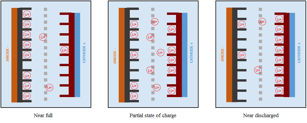
One crucial point to mention is the formation of a solid electrolyte interphase (“SEI”) layer that forms on the anode the very first time a Li-ion cell is charged. Typical organic solvents used in electrolytes (e.g., ethylene carbonate and dimethyl carbonate) react readily with graphite and result in the formation of a SEI layer on the anode. The SEI layer, which is almost impenetrable to electrolyte molecules, then prevents further side reactions from occurring - hence impeding growth of the SEI layer.
The SEI layer is ionically conductive but electronically insulating; lithium ions can pass through the SEI and intercalate in the graphite. However, the formation of the SEI layer consumes lithium ions - with fewer lithium ions to take part in the reactions at the electrodes, formation of the SEI results in irreversible capacity loss of the Li-ion cell. As we will see later, the SEI layer can grow over time and contribute to degradation of the Li-ion cell. Growth of the SEI layer also consumes the electrolyte solvent and increases the internal resistance of the cell, hence resulting in power fade.
Overall, there are a few charging regimes which can be applied to a Li-ion cell:
Constant current - the voltage applied to the battery is varied while the current remains constant;
Constant voltage - voltage applied is constant until the current becomes close to zero; and
Random - this happens in certain situations where charging is uncontrolled. For example, regenerative braking in EVs generates power spikes which must be absorbed by the battery.
In general, the charging profile of a Li-ion battery is the constant current phase followed by the constant voltage phase. In the constant current phase, the voltage of the battery increases until it reaches the desired end-of-charge level. Once the desired end-of-charge voltage is reached, the constant voltage phase kicks-in and the current gradually decreases until it is close to zero. At this point, applying a charging voltage to the battery will overcharge it and will hasten degradation of the battery (as discussed below).
Discharging a Li-ion cell
When a Li-ion cell is discharged, lithium ions move from inside the graphite anode, pass through the electrolyte, and then reach the cathode. On the other hand, electrons move from the anode via the external circuit to the cathode.
The reaction at the cathode is:
While the reaction at the anode is:

The above reactions are essentially the reverse of the charging process, and the anode is said to be “delithiated”.
Note that in Li-ion cells, the amount of energy stored is directly related to the volume of the electrodes while the power is related to the surface area. Because the volume and surface area of the electrodes are inherently linked, energy and power of Li-ion cells are linked.
Considerations during charging and discharging
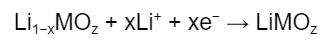
Firstly, the temperature of the Li-ion cell during the charging and discharging process greatly influences the charging time, discharge capacity and C Rate of the Li-ion cell.
To recap, lithium ions have to intercalate into the graphite matrix during charging. They are initially inserted at the surface of porous graphite anode and then move deeper into the graphite matrix. This process requires time and creates a limit at which a Li-ion cell can absorb lithium ions; as a result, there is a limit on the charging current. If this limit is exceeded, lithium gets deposited on the anode instead of intercalating into it - this is known as lithium plating. At lower temperatures, the intercalation reaction starts getting slowed down - hence, the maximum permissible current so that lithium plating does not occur drops with temperature.
As Figure 3 illustrates, the maximum charge rate to avoid lithium plating drops with decreasing temperature. At the same time, charging time increases with decreasing temperature.
Temperature also affects the maximum discharge capacity of Li-ion cells. Figure 4 shows that as temperature drops, the maximum range that a Li-ion battery can provide drops. One way to understand this is that lithium ions are less energetic at lower temperatures and hence more difficult to ‘extract’ from the graphite matrix. Hence, some capacity is ‘locked in’ and not available to be discharged for use.
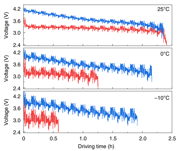
Secondly, all Li-ion cells have internal resistance - this arises from anything which impedes the movement of ions (i.e, ionic resistance) or electrons (i.e., electrical resistance). The former can occur in the electrodes and/or the electrolyte, while the latter can occur in the electrodes and/or current collectors.
The internal resistance of the battery leads to a few implications. For one, round-trip efficiency, which is defined as the percentage of electricity put into storage that is later available for discharge, is always less than 100%. Some fraction of energy stored must be used to overcome the internal resistance and this is dissipated as heat.
Internal resistance also causes the voltage at the terminals to be lower than the true voltage as there is a drop in potential across the internal resistance. Figure 5 provides a good illustration of this.
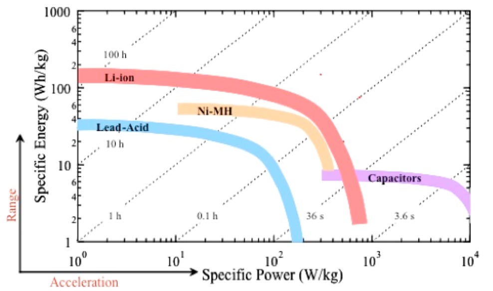
Thirdly, the rate at which a Li-ion cell is discharged (i.e., the power) is inversely correlated with the amount of energy that the cell can provide. The well-known Ragone Plot (Figure 6) illustrates that the higher the power, the lower the amount of energy a battery can provide. The reason for this is that as power increases, heat losses increase, and this reduces the useful amount of energy available.
Li-ion cells, modules and packs
Types of cells
In general, there are 4 types of Li-ion cells:
Cylindrical
Prismatic
Pouch
Coin
Cylindrical cells, illustrated in Figure 7, have high volumetric energy density and are generally cheaper to manufacture than prismatic cells for a given capacity. They are also very robust, resilient to mechanical damage, and can tolerate a higher level of internal pressure as the round cross-section allows pressure to be distributed rather evenly across the circumference.
However, cylindrical cells suffer from poor packing efficiency (see Figure 8). Yet, this is advantageous when it comes to thermal management as the spaces allow for better heat dissipation.
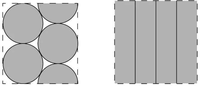
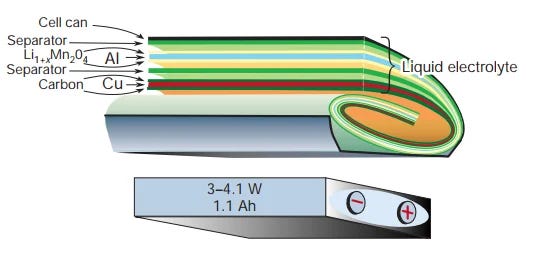
Prismatic cells consist of sheets of anodes, cathodes and separators sandwiched, rolled up or stacked, and pressed to fit into a casing in cuboid form (see Figure 9). As Figure 8 shows, the cuboid shape allows for optimal packing efficiency; however, thermal management is more challenging than in cylindrical cells as there are no air gaps for better heat dissipation.
Pouch cells, as shown in Figure 10, do not have a rigid casing and use a sealed flexible foil as the container. The anodes, cathodes and separator are stacked inside the foil and maximize the space available. While the pouch cell design allows for low weight, high energy density and ability to easily fit the space required, its soft construction means it cannot be placed near sharp objects and supporting structure is needed.
Lastly, coin cells are typically used in small consumer electronics (e.g., watches). This is the form factor used in labs when researchers want to first test new battery materials and their corresponding performance parameters.
Cells, modules and packs
Figure 11 shows the relationship between cells, modules and packs. Essentially, a pack consists of multiple modules, and each module consists of multiple cells.

To produce modules, multiple cells are encased in a mechanical structure and connected in series and/or parallel. The casing protects the cells from external shocks, heat or vibration. Within the module, insulators/heat shields can be placed between cells to reduce inter-cell heat transfer and active cooling systems can be incorporated into the module for better heat dissipation - both these measures can be important in preventing thermal runaway.
Packs are then produced by connecting multiple modules together in series and/or parallel. The thermal management solutions within modules can also apply to packs - i.e. insulators and heat shields can be placed between modules, and cooling systems can also be incorporated.
At the pack-level, sensors and controllers such as the battery management system (discussed below) are also connected to the battery.
Although modules and packs are typically present in most Li-ion batteries, innovations are occurring that may render the module and/or pack obsolete. For example, companies are starting to embrace cell-to-pack technology (“CTP”) wherein cells are directly integrated into the pack without modules (see Figure 12) - this increases space utilization and hence gravimetric and volumetric energy density at the pack-level.
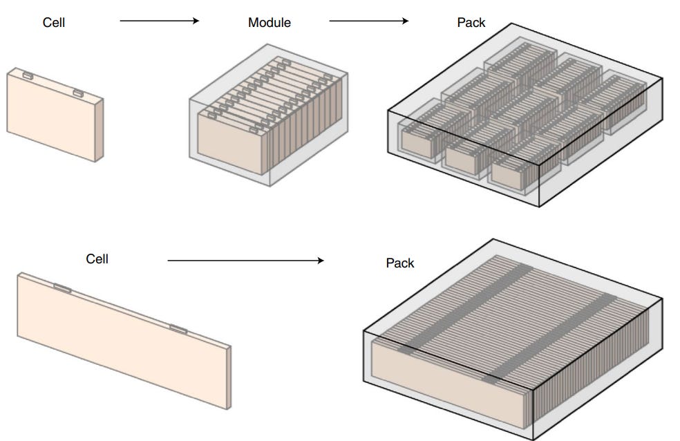
Conventionally, cells take up 80% of a module’s volume, and modules take up 50% of the pack’s volume; hence cells comprise approximately 40% of a pack’s volume. Using CTP technology, BYD’s Blade battery is designed such that cells take up about 60% of pack volume. The CTP technology also results in improvements in the gravimetric cell-to-pack (“GCTP”) ratio (or the ratio of specific energy at the pack level to that at cell level). While most EVs have a ratio of 0.55 - 0.65, the Blade battery has a ratio of 0.85. Note that the ratios are less than 1 as other components (e.g., battery management system, thermal management system, cables) take up space and weight in the pack.
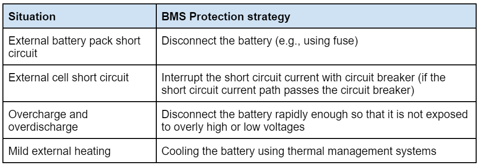
Battery management system
The battery management system (“BMS”) monitors and regulates the Li-ion cells to ensure that they operate within safe conditions. It comprises of:
Software: data collection and estimation, cell balancing, charge control, etc.
Hardware: sensors to track multiple parameters (e.g., temperature at various places within the module), circuits to prevent overcharging, overheating and over-discharging, and potentiostat / galvanostat to measure/control voltage and current.
The BMS is important because it can act to mitigate problems, as the table below (adapted from RISE Research Institutes of Sweden AB) shows:
Chemistries of anodes
As mentioned, the electrochemical potential difference between the cathode and anode influences the voltage of a Li-ion cell. Given that transition metal ions at the cathode are reduced during the discharging process, we therefore want a material for the anode that has high reducing power. Lithium metal is one of the strongest reducing agents around and therefore the reduction potential of anode materials is often compared to lithium.
Figure 13 shows some commonly used materials for anodes. Carbon is an attractive material to use because its reduction potential is close to lithium metal. Other reasons that graphite is commonly used as an anode material include:
Relatively low volume change of 10% during lithiation / delithiation;
Good lithium ion diffusivity;
Good electrical conductivity; and
Low cost.
Carbon therefore offers a good balance of low cost, good mechanical stability, and moderate energy density.
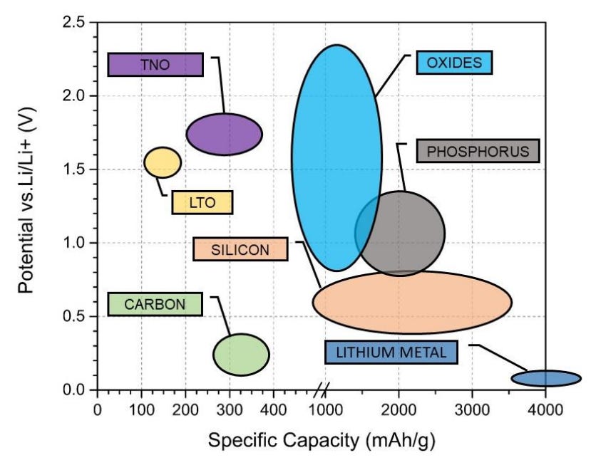
Other materials being explored for anode materials include silicon and lithium metal. While silicon has high specific capacity and a potential that is relatively close to lithium - hence allowing silicon anodes to have high energy density - silicon undergoes huge volume expansions of 270% during the lithiation and delithiation process. As we will explore later, this volume change creates mechanical stress which can lead to electrode fractures. This may expose ‘fresh’ anode surfaces for the SEI layer to form, hence consuming lithium ions and resulting in capacity fade.
As for lithium metal, it also has high specific capacity and strong reducing power. However, volume expansion is also an issue - the expansion can lead to cracking of the SEI and the formation of lithium metal dendrites during cycling, and potentially lead to an internal short circuit.
Chemistries of cathodes
As discussed, the difference in electrochemical potential between the cathode and anode is ideally maximized (within reasonable limits of cell stability) to increase the voltage of the Li-ion cell. We therefore want cathode materials that are strongly oxidizing (i.e., to easily accept electrons during the discharging process), which is the opposite from what we want in an anode material.
Introduction to common cathode materials
Some of the more common cathode materials are indicated here:
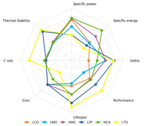
The characteristics of cathode chemistries are often compared on a spider chart such as the one in Figure 14. This shows that nickel-based chemistries (i.e. NMC and NCA) have higher specific energy and specific power than LFP batteries. On the other hand, LFP batteries have better thermal stability and safety.
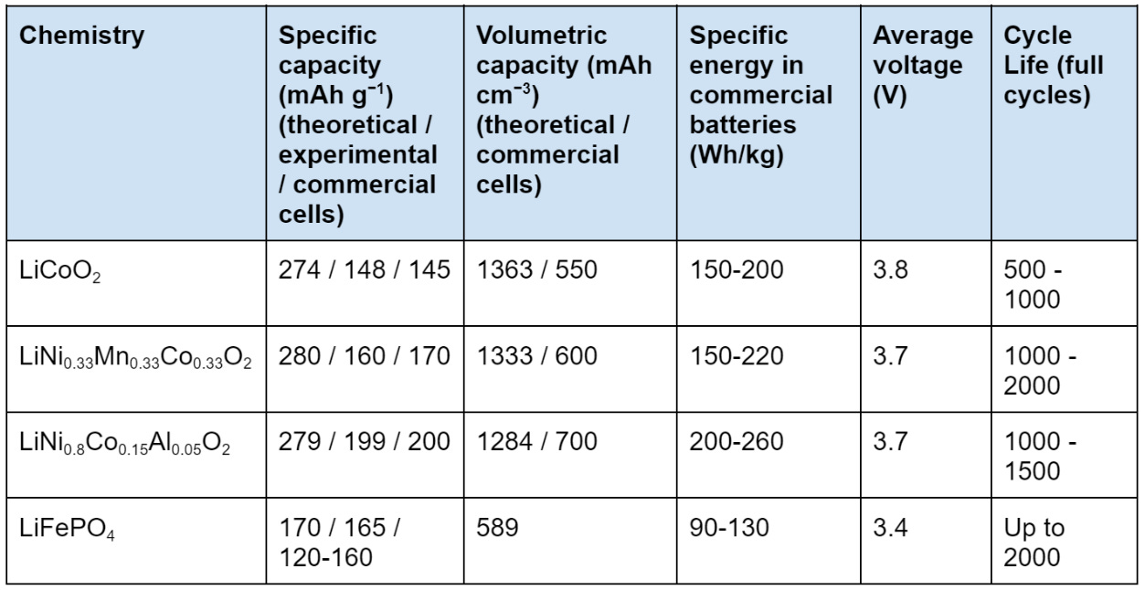
To be more precise, the capacities and specific energies of some of the cathode chemistries above can be summarized in the table below (adapted from Nitta et al., Hu et al. and Zhang et al.):
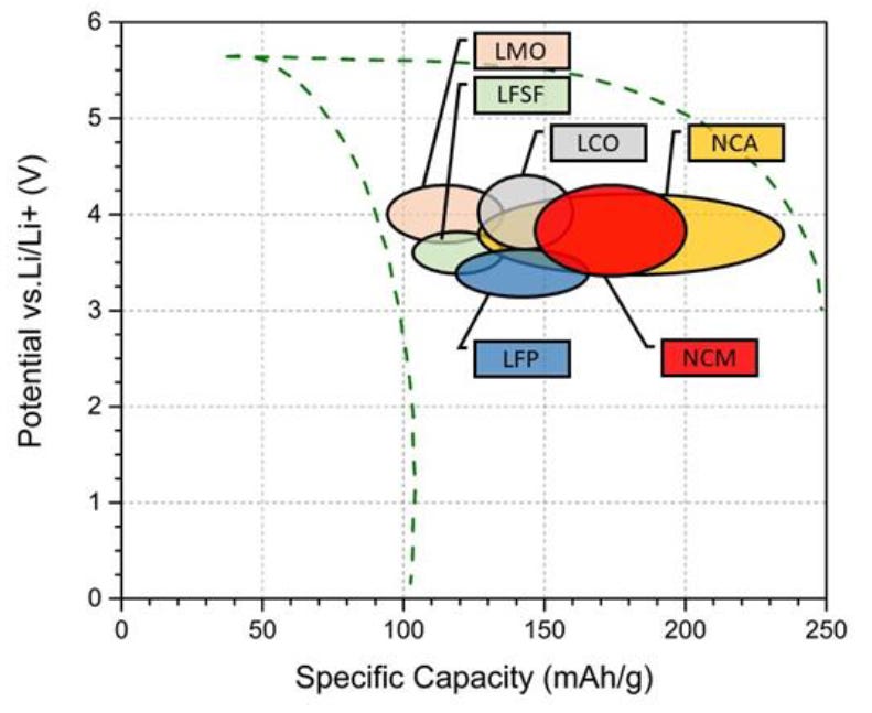
This can be explained by Figure 15, which illustrates how NCM, NCA and LCO all have higher electrochemical potential than LFP, and how NCA and NCM have a higher specific capacity than LFP.
Considerations for cathode materials
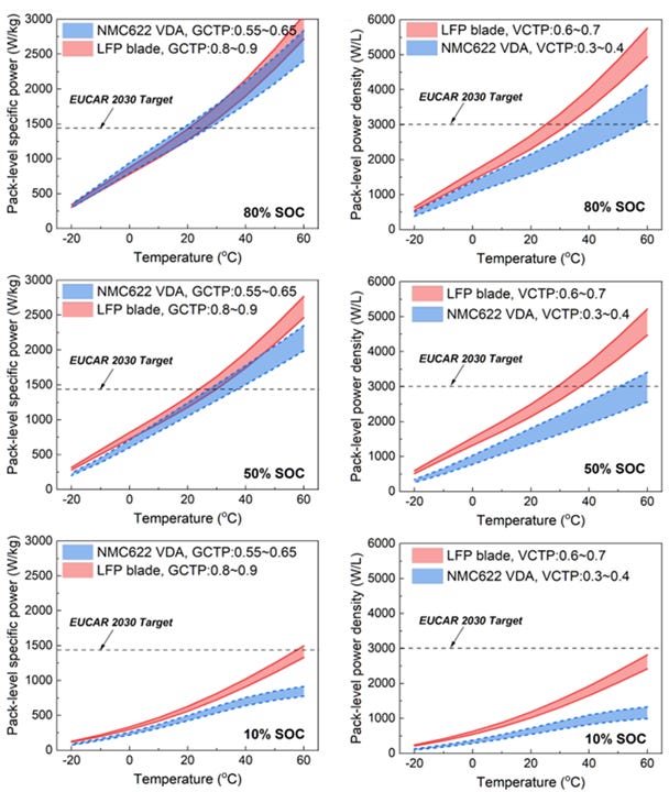
Firstly, the above cell-level numbers do not necessarily translate to the same performance at the pack-level. As discussed, companies are increasingly adopting CTP technology. The implication here is that although LFP cells may have poorer specific power and energy density at the cell-level, in some instances they may be superior at the pack-level.
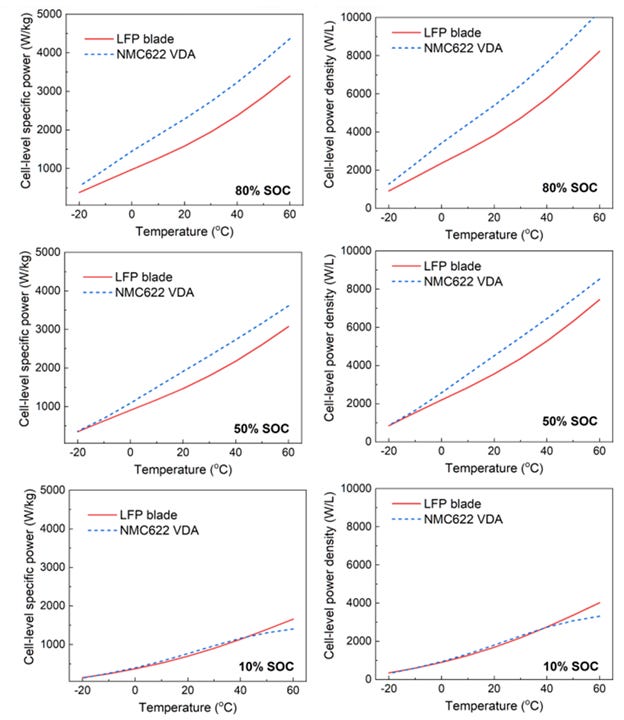
For example, while BYD’s Blade battery demonstrates lower cell-level specific power and power density (see Figure 16), it has comparable or superior performance at the pack-level to NMC622 VDA cells (see Figure 17). This is largely because the BYD Blade battery has a higher GCTP ratio of 0.8 - 0.9 (versus 0.55 - 0.65 for the VDA NMC622) and a higher volumetric cell-to-pack (“VCTP”) ratio of 0.6 - 0.7 (versus 0.3 - 0.4 for the VDA NMC622).
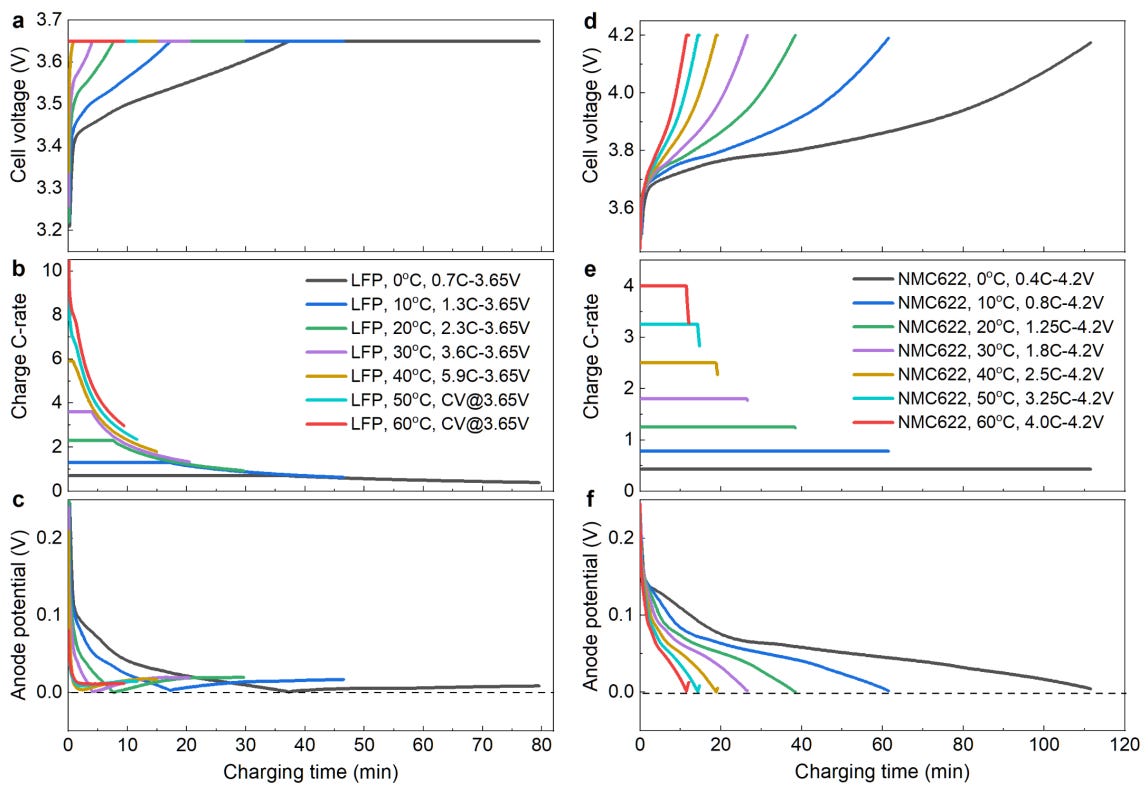
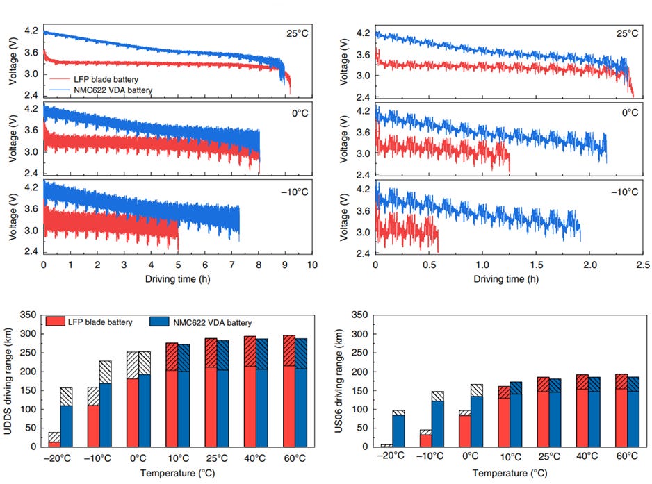
Capacity of the Blade battery is also comparable to that of the VDA NMC622 battery. When both batteries were used in an EV under city-driving scenarios, the Blade battery generally showed comparable driving durations (see Figure 18). However, the performance of the BYD Blade battery was inferior at -10°C - Yang et al. attributed this to the significant drop in ionic diffusivity and electrolyte conductivity for the LFP battery at lower temperatures, hence resulting in higher ionic resistance and greater electrolyte transport resistance. However, Yang et al. also indicated that it is possible to thermally modulate the LFP battery so that performance is comparable to the VDA NMC622 battery.
Secondly, as Figure 14 shows, nickel-based chemistries (i.e., NCA and NMC) have higher specific power and specific energy than LFP cells, but this comes at the expense of poorer thermal stability and lifespan.
Nickel-based chemistries have higher specific energy than LFP cells because the redox activity of nickel generally occurs at higher potential than iron. Hence, the higher the concentration of nickel, the higher the energy density. LFP cathodes also have lower specific power because they generally have poorer transport of lithium ions and electrons through the crystal structure, hence resulting in higher cell resistance.
However, as the concentration of nickel increases, the following performance parameters tend to suffer (see Figure 19):
Thermal stability;
Capacity retention over time; and
Structural stability.
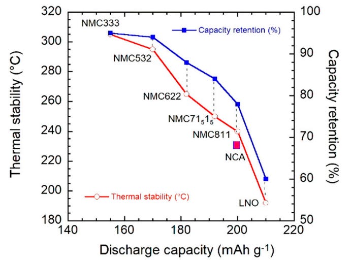
Thermal stability tends to worsen as nickel concentration increases because Ni-O bonds are weaker. Hence, at charging voltages above 4.3V or when operating temperature exceeds 40°C, the Ni-O bond may break and release oxygen. The oxygen may then react with the electrolyte, resulting in exothermic reactions and potentially causing thermal runaway.
Furthermore, Ni3+ and Ni4+ ions are strongly oxidizing and tend to react with the electrolyte. This leads to the formation of a cathode-electrolyte interphase layer that introduces additional impedance for diffusion of lithium ions, and also results in capacity loss. When Ni3+ or Ni4+ ions are reduced to Ni2+ ions, there is also a tendency for Ni2+ ions to migrate to vacant sites in the ionic crystal lattice that Li+ ions typically occupy because the ionic radius of Ni2+ ions and Li+ ions are similar. This mixing of cations can result in structural instability of the crystal structure and also lead to structural transformation. Hence, both capacity retention and structural stability are affected.
However, LFP cells have a narrower temperature range than NCM and NCA cells. As Figure 4 shows, the available capacity for LFP cells drops much faster than a NCM cell as temperature drops.
Third, with most Li-ion cells today using graphite anodes, cathode chemistry is one factor that influences cycle life (beyond other operating parameters such as charging rate, operating temperature, state of charge (“SoC”) and depth of discharge (“DoD”)). Cycle life, which is typically taken to be the number of times a battery can charge and discharge before it reaches 80% of its initial capacity, can be represented by Figure 20 for various chemistries.
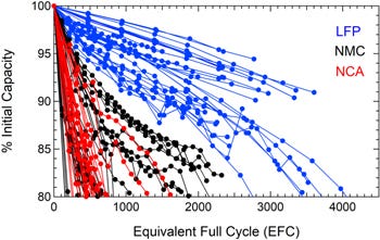
LFP cells demonstrate better cycle life than NMC and NCA cells. As discussed earlier, nickel-based cathodes have poorer capacity retention and structural stability than LFP cathodes.
Note that SoC differs from state of health (“SoH”) - while SoC is ratio of the remaining charge in the battery divided by the battery’s maximum deliverable charge at that point in time, SoH is ratio of the maximum battery charge to its rated capacity.
Fourth, all things being equal (e.g., temperature and SoC), LFP cells tend to have longer calendar life than NCM and NCA cells. Geisbauer et al. studied calendar aging for Li-ion cells of various chemistries - in general, LFP cells demonstrate better capacity retention than NCM and NCA cells when subject to calendar aging.
Lastly, LFP cells generally have higher round-trip efficiencies than NCM and NCA cells (the higher the round-trip efficiency, the less energy is lost in the storage process). Preger et al. discovered that LFP cells show higher round-trip efficiencies than NCA and NCM cells at multiple cycling conditions. The decrease in round-trip efficiency over multiple cycles is attributed to the increase in cell resistance as the SEI grows over time.
Degradation and aging
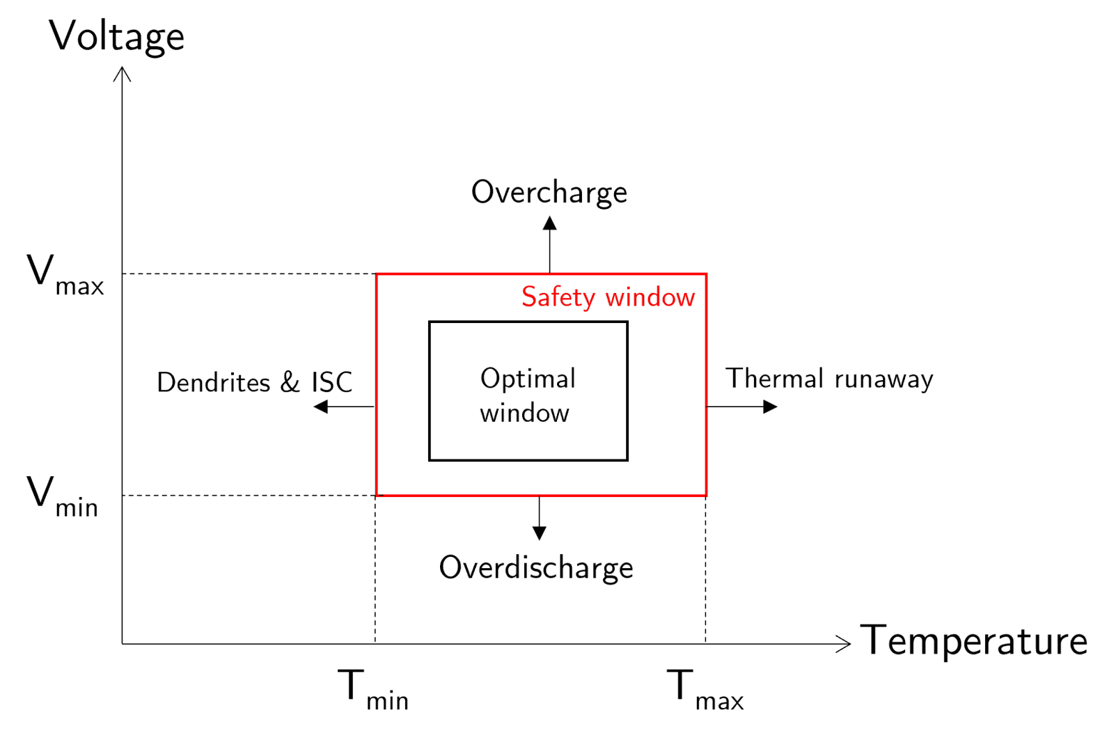
To ensure that Li-ion batteries function optimally and have maximal lifespans, they must be operated within a range of operational parameters (Figure 21). The more a Li-ion battery is operated beyond the optimal window, the more it degrades and the more likely thermal runaway can occur.
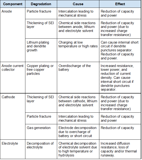
To understand degradation mechanisms, we can segment them by component as shown in the table below (source: adapted from Hendricks et al.)
Anode
Firstly, particle fracture can occur at the anode. During operation of a Li-ion cell, intercalation and deintercalation take place repeatedly. This insertion and removal of lithium ions from the graphite lattice results in volume change of the anode and creates mechanical stress on the graphite lattice. Over time, as many intercalation and deintercalation cycles take place, the mechanical stress results in the formation and/or propagation of microcracks. These cracks can then expose fresh anode surfaces for side reactions and the formation of new SEI layers, hence reducing capacity.
There are a couple of considerations for particle fracture as a degradation mechanism:
Temperature: at high temperatures, thermal stresses come into play and accelerate particle fracture. At low temperatures (e.g, below 0 °C), graphite becomes brittle and hence more susceptible to fracture.
Current: at high currents, the rate of intercalation and deintercalation is higher, resulting in generation of mechanical stresses at accelerated rates and hence a faster rate of degradation.
SoC: the higher the SoC, the higher the relative volume expansion of the graphite lattice from its delithiated state, and hence the higher the mechanical stress generated.
DoD: a greater DoD results in greater volume change during cycling, hence generating more mechanical stress.
Manufacturing processes can lead to microcracks even before the Li-ion cell is used. During cycling, stresses can concentrate at these crack tips and accelerate fracture through crack propagation.
Secondly, as a Li-ion cell is repeatedly cycled, thickening of the SEI layer can occur. As discussed, the SEI layer is first formed when a Li-ion cell is first charged. While the formation of the initial SEI layer tends to impede its further immediate growth, the SEI layer can grow over time due to:
Particle fracture due to mechanical stress results in ‘fresh’ graphite sites available for reaction with the electrolyte solvent; and
Storage of the Li-ion cell at elevated SoC. As the SoC increases, the cell voltage also rises - this makes the electrodes more chemically reactive and encourages side reactions with the electrolyte. Hence, storage of the Li-ion cell over time (i.e., calendar aging) will result in the thickening of the SEI layer, resulting in capacity and power fade.
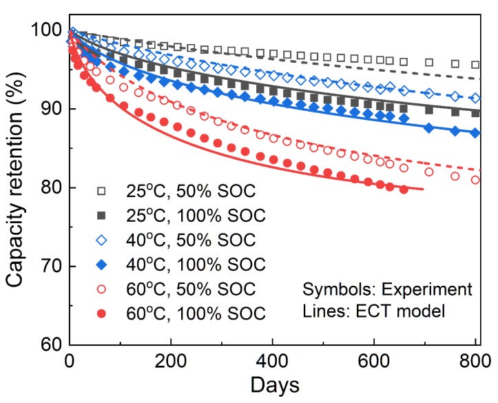
In general, the growth of the SEI layer is accelerated at higher SoC and temperatures (Figure 22). Higher temperatures result in faster reaction times, faster parasitic side reactions, and hence faster growth of the SEI layer. Higher SoC means that the Li-ion cell is stored at higher voltages, and this encourages side reactions between the electrodes and electrolyte. Although Figure 22 is for an LFP cell, Preger et al. found that regardless of battery chemistry, capacity fade consistently increased with SoC and temperature in calendar aging studies (where SEI layer growth is the dominant degradation mechanism).
Third, lithium plating can occur - this happens when lithium metal forms on the surface of the anode instead of intercalating into it. There are typically two mechanisms under which lithium plating can occur:
When the anode is fully lithiated, overcharging a Li-ion cell results in lithium plating because the lithium ions have nowhere else to go; and
When the Li-ion cell is charged at a rate too fast relative to its temperature. In general, lithium plating occurs if the intercalation reaction is too slow relative to the charge rate, hence increasing the rate of the lithium plating reaction. Note that as temperatures fall, the intercalation reaction becomes slower, and hence the maximum permissible current so that lithium plating does not occur also drops (i.e., charge rates that are acceptable at normal temperature become too high at very cold temperatures).
There are a few things to note about lithium plating:
Lithium plating also contributes to pore blockage of the anode - this makes it more difficult for lithium ions to intercalate and insert into the graphite matrix, making it even likelier that lithium plating occurs. Hence, lithium plating is self-reinforcing.
Lithium plating can result in growth of metallic dendrites - these dendrites can puncture the separator and lead to an internal short circuit, increasing the cell temperature and potentially causing thermal runaway.
Anode current collector
Overdischarge of a battery (when a battery reaches its minimum voltage) can result in the copper at the anode current collector dissolving and being deposited on the cathode and anode. With less copper as a conducting material, resistance of the Li-ion cell increases, resulting in power fade.
Furthermore, copper plating at the anode hinders the flow and intercalation/deintercalation of lithium-ions during charge and discharge, and this can further encourage lithium plating. Both copper plating and lithium plating reduce the porosity of the graphite anode, further impeding intercalation/deintercalation, increasing the resistance of charge transfer, and hence resulting in power fade.
If the deposition of copper results in the formation of dendrites, an internal short circuit may occur if the dendrites puncture the separator.
Cathode
Firstly, a SEI layer can also form on the cathode surface. As previously discussed, Ni3+ and Ni4+ ions are strongly oxidizing and tend to react with the electrolyte. This leads to the formation of a cathode-electrolyte interphase layer that introduces additional impedance for diffusion of lithium ions, and also results in capacity loss.
Secondly, particle fracture happens at the cathode in a manner similar to that at the anode. Over time, this can further accelerate the growth of the SEI layer at the cathode.
Lastly, at high SoC and voltages, nickel-rich cathodes can become unstable. This can result in the decomposition of the cathode and oxidation of O2- in the crystal lattice. Oxygen atoms released can form oxygen gas or oxidize ethylene carbonate to produce gases like carbon dioxide and carbon monoxide.
Electrolyte
The electrolyte degrades in two main ways - thermal decomposition and hydrolysis.
Thermal decomposition of the electrolyte starts at 70°C and accelerates at higher temperatures. At 85°C, EC and DMC (both solvents in the electrolyte) react to form products such as dimethyl-2,5-dioxahexane carboxylate (DMDOHC). Gases that are formed from decomposition of the electrolyte can raise the internal pressure of the Li-ion cell and increase the temperature, potentially leading to thermal runaway.
On the other hand, hydrolysis is a chemical reaction that occurs when chemicals react with water. In a Li-ion cell, the LiPF6 electrolyte salt typical exists in a equilibrium reaction with LiF and PF5:

Under typical conditions, the equilibrium lies further to the left. However, in the presence of water, the equilibrium starts shifting to the right.
Moving the equilibrium to the right results in the formation of LiF, an insoluble and electronically insulating salt. This can deposit on the anode, impending intercalation/deintercalation, reduce concentration of lithium ions, and hence result in capacity and power fade.
The formation of PF5 can subsequently lead to the formation of hydrofluoric acid via this reaction:

Hydrofluoric acid can then react with the cathode and result in a loss of active cathode material.
Thermal runaway
Thermal runaway is a phenomenon in which the temperature of a Li-ion cell rapidly rises in an uncontrolled manner. This usually happens when exothermic reaction(s) generate sufficient heat, which in turn allow more exothermic reactions to occur that then generate more heat. This set of chain reactions result in loss of thermal stability of the Li-ion cell and it is unable to dissipate heat as quickly as it is being generated.
Different Li-ion cells have different thermal runaway threshold temperatures. For example, LFP cells are much more thermally stable than nickel-based cells. In other words, thermal runaway for LPF cells only sets in at a higher temperature as compared to cells of nickel-based chemistries.
The bullet points below illustrate the series of reactions in a Li-ion cell as temperature progressively increases (source: Zhang et al. and Jian et al.).
>90°C: SEI layers begin to decompose; this releases heat and increases the temperature of the Li-ion cell.
>130°C: The separator begins to melt. If the electrodes make contact as a result of the separator losing its structural integrity, an internal short circuit can occur.
>150°C: LCO cathodes begin to break down and release oxygen gas.
>160°C: NCA cathodes begin to break down and release oxygen gas.
>180°C: NMC cathodes begin to break down and release oxygen gas.
>200°C: The electrolyte decomposes and gases are released.
>310°C: LFP cathodes begin to break down and release oxygen gas.
Across Li-ion cells of various chemistries, there are multiple factors that can initiate thermal runaway, as Figure 23 shows.
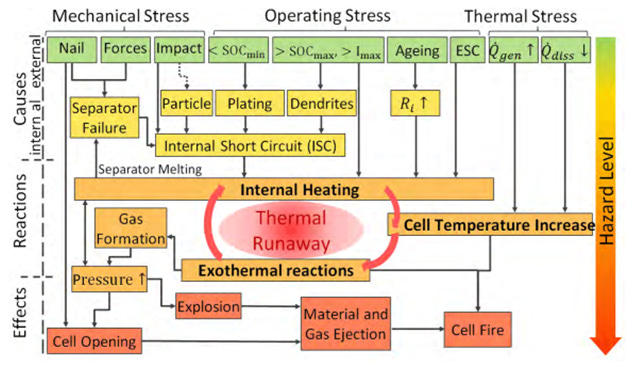
Mechanical stress factors - nails (or sharp objects) and external forces - can puncture the separator and lead to an internal short circuit when the cathode and anode connect electrically. When this happens, the current is very high and the temperature rises.
Operating stress factors include:
<SoCmin: this refers to over discharging a battery - as discussed, this can lead to the formation of copper dendrites which can puncture the separator, leading to an internal short circuit.
>SoCmax , >Imax: Overcharging a Li-ion cell such that the voltage or SoC is more than the maximum may lead to lithium plating and the formation of dendrites. At charging currents that are too high relative to the cell’s temperature, lithium plating can also occur.
Aging: as a Li-ion cell ages, the internal resistance of the cell increases due to the growth of the SEI layers, consumption of the electrolyte due to side reactions, and reduced porosity of the electrodes. As internal resistance increases, more heat is generated inside the cell during a Li-ion cell’s operations.
External short circuit (“ESC”): high current leads to high cell temperature
Lastly, thermal stress - from both external and internal heat sources - can increase the temperature of the Li-ion cell, and reduce the net rate at which a Li-ion cell can dissipate heat away. Overall, the temperature of the Li-ion cell increases.
Strategies to mitigate Li-ion battery failure
Overall, methods to mitigate failure of Li-ion cells can be classified into five categories, as Figure 24 shows.
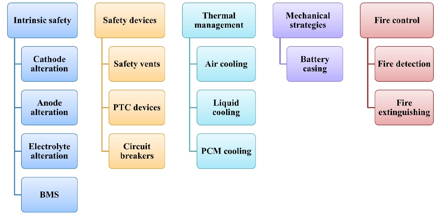
Methods to improve intrinsic safety include:
Cathode alteration: this includes surface coatings of the cathode to improve stability during cycling. In doing so, formation of SEI layer, particle fracture and cathode decomposition may be impeded. Furthermore, doping of the transition metal oxide lattice may be performed to increase the structural and thermal stability of the cathode.
Anode alteration: surface coatings (e.g., using atomic layer deposition) to coat the anode surface in a conformal manner can improve cycling performance and thermal stability. Additives used in the anode composite can also enhance stability of the SEI layer.
Electrolyte alteration: additives can be added to the electrolyte to improve overall properties of a Li-ion cell by, for example, impeding growth of the SEI layer.
BMS: the BMS plays an important role by monitoring the battery’s health, running diagnostics, identifying and predicting failures, and adopting counter-measures to ensure battery safety.
Safety devices include:
Safety vents to release excess pressure inside the battery beyond a safety threshold when gas is generated.
Positive thermal coefficient (“PTC”) devices: these operate on the principle that resistance of the device increases with temperature. Hence, if a Li-ion cell is overheated, the PTC device will restrict the current - this should inhibit further temperature increase. Note that under normal operating conditions, a PTC device should have negligible resistance.
Circuit breakers include devices such as magnetic switches or bimetallic thermostats that cut-off the circuit in the event of excessive heat and/or current.
Thermal management methods include:
Air cooling and liquid cooling
Phase change method (“PCM”) cooling: this operates on the principle that as the PCM material absorbs heat, it changes state from solid to liquid. Once heat is removed from the material (and the battery), the PCM material reverts back to a solid state.
Lastly, mechanical methods to prevent battery failure typically involve optimizing the battery casing to shield the interior from mechanical forces. For example, the casing can have shock absorbers to cushion the impact of any incoming force.
Key takeaways
Li-ion batteries generate electricity through redox reactions which occur because the redox potential between the cathode material and anode material is different. These redox reactions allow the conversion between electrical and chemical potential energy and the storage of the latter in the electrodes.
Intercalation and deintercalation is the mechanism through which Li-ion cells work and there are limitations. During charging, lithium ions move from the cathode and intercalate into the anode. During discharging, the reverse occurs - lithium ions move from the anode back to the cathode where they recombine with electrons. The rate of the intercalation/deintercalation reaction slows down with lowered temperature, affecting the maximum charging rate and discharge capacity.
There are multiple cathode chemistries and each have their pros and cons. For example, nickel-based chemistries have higher specific power and specific energy than LFP cells, but this comes at the expense of poorer thermal stability and lifespan. At the same time, while LFP cells have a narrower operating temperature range than nickel-based chemistries, they also have comparatively longer cycle and calendar life.
Li-ion batteries should ideally be operated within a certain temperature and voltage range to minimize degradation and reduce the odds of failure. At operating parameters beyond this range, degradation is accelerated and may even lead to catastrophic failure (e.g., thermal runaway).
–
That’s it for this primer on conventional Li-ion batteries. Thanks for reading!